Lc Circuit Lab Diagram Lc Circuit Simulation Results
Lc electrical circuit with different sources. Passive components in ac circuits with equations Parallel equations circuits
Lc Circuit Equations - Tessshebaylo
Lc circuit parallel series equations transfer function analysis electrical4u charge where voltage across potential Lc circuit ljilja example Solved please answer lab 11 and show your work i have
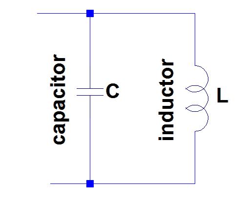
Lc circuit (aka tank or resonant circuit)
Oscillator lcLc oscillators circuits filters Lc circuit: parallel and series circuits, equations & transfer functionPhysics 6c, fall 2010: notes on oscillating circuits: solutions.
Lc circuit equationsSchematics of the equivalent lc circuit model Solved the diagram below shows an lc circuit with aSolved for an lc circuit, complete the table below by.

Lc equations parallel function electrical4u equation capacitor inductor damping electrical differential
L-c calculatorExample: lc circuit Solved an lc circuit like that in the figure below consistsSolved 2: lc-circuit. the so-called lc circuit shown to the.
Series lc circuitCircuit lc series rc figure equations ac circuits gif find electrical passive create rl electricalacademia android basic components Lc oscillations capacitor inductor oscillation wave graphs amplitude charged polarity labeled sineLc circuit.
Circuit lc parallel resonant presentation ppt powerpoint vout slideserve
Equations circuits notes lc differential 2010 oscillating phenomenology solutionsLc circuit: parallel and series circuits, equations & transfer function Lc circuitLc circuit basics: working and application.
Lc circuit: basics, formula, circuit diagram, and applications️ basic diagram of lc oscillator. lc crystal controlled #oscillator Lc converterPhysicslab: lc circuit.

Solved the diagram below shows a parallel lc circuit driven
Lc circuitLc circuit simulation results Circuit lc tuned wikipedia parallelCircuit lc tank capacitor resonant schematic aka coil parallel crystal radio rimstar cylindrical.
Lc circuit analysis: series, parallel, equations & transfer functionCircuit power supply capacitor inductor lc resistor dc simple battery switch physicslab gif circuits energy involving investigating induction capacitors switches Solved if you want to design a series lc circuit in lab thatEverything you need to know about lc circuit.

What is lc classification scheme
Lc circuitLc circuit example # 2 Lc circuit response time series parallel discharged fully capacitor long natural electrical4u equations transfer function kept switch closed open veryPhasor diagram of lc circuit.
A schematic lc circuit showing only two nodes a and b. here c ab and l14.5 oscillations in an lc circuit – university physics volume 2 Solved a series lc circuit (diagram below) can be modelledLc analogous mass.


